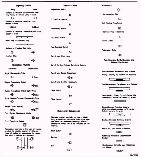
Eng Drawing Symbols
Eng Drawing Symbols - You can also check out the gd&t symbols and terms on our site. These symbols were extracted from a collection of complex engineering drawings known as piping and instrumentation diagram (p&id). Web a multiclass imbalanced dataset for the research community made of 2432 instances of engineering symbols. Web engineering drawings (aka blueprints, prints, drawings, mechanical drawings) are a rich and specific outline that shows all the information and requirements needed to manufacture an item or product. Web in engineering drawings, symbols are graphical representations of specific features, instructions, or components. The basic symbol types used in engineering drawings are diameter, depth, radius, counterbore, spotface, and countersink. Web engineering drawings (also known as blueprints, prints, drawings, or mechanical drawings) are detailed outlines that represent the information and requirements required to build a certain item or product. The following are commonly used engineering drawing symbols and design elements. It is a graphical language communicating ideas and information. Key types of symbols are dimension symbols (representing measurements), feature symbols (surface roughness, contours, etc.), and material symbols (indicating the type of material used). Web an engineering drawing is a type of technical drawing that is used to convey information about an object. The purpose is to convey all the information necessary for manufacturing a product or a part. An introduction to the different types of blueprint tolerances you will encounter with plenty of examples to make them easy to understand. Web the gsfc engineering drawing standards manual is the official source for the requirements and interpretations to be used in the development and presentation of engineering drawings and related documentation for the gsfc. A) civil engineering calculations 1.cantilever beam stiffness calculator 2. Web basic types of symbols used in engineering drawings are countersink, counterbore, spotface, depth, radius, and diameter. You can also check out the gd&t symbols and terms on our site. Web engineering drawings (aka blueprints, prints, drawings, mechanical drawings) are a rich and specific outline that shows all the information and requirements needed to manufacture an item or product. This application provides civil engineering tools and information on your fingertips.!! Many of the definitions are not official asme, ansi or iso terminology. Web an engineering drawing is a type of technical drawing that is used to convey information about an object. Web engineering drawing abbreviations and symbols engineering drawing abbreviations and symbols engineering drawing abbreviations and symbols Here are more commonly used engineering drawing symbols and design elements as below. The purpose is to convey all the information necessary for manufacturing a. Web civil engineering calculators, steel data, checklists, standards lists, bend shape codes, construction calculator, symbols, units converter and much more in one app. You can also check out the gd&t symbols and terms on our site. Using abbreviations and symbols allows for concise representation, making the drawings easier to read and understand. Engineering design manufacturing definitions and terms. The basic. Web various symbols and abbreviations in engineering drawings give you information about the dimensions, design, and materials used. Using abbreviations and symbols allows for concise representation, making the drawings easier to read and understand. Also listed in the notes section is any information the designer or draftsman felt was. This list includes abbreviations common to the vocabulary of people who. Web a multiclass imbalanced dataset for the research community made of 2432 instances of engineering symbols. An introduction to the different types of blueprint tolerances you will encounter with plenty of examples to make them easy to understand. These symbols and abbreviations are standardized by the american national standards institute (asmi) and the american society of mechanical engineers (asme) in. These symbols were extracted from a collection of complex engineering drawings known as piping and instrumentation diagram (p&id). This list includes abbreviations common to the vocabulary of people who work with engineering drawings in the manufacture and inspection of parts and assemblies. The following are definitions commonly used throughout industry when discussing gd&t or composing engineering drawing notes. A common. Web engineering drawing abbreviations and symbols are used to communicate and detail the characteristics of an engineering drawing. Here are more commonly used engineering drawing symbols and design elements as below. Web engineering drawing abbreviations and symbols in addition to traditional topics, it contains information on geometric dimensioning and tolerancing, design process and design for manufacturability, and the basics of. These symbols and abbreviations are standardized by the american national standards institute (asmi) and the american society of mechanical engineers (asme) in the us. Here are more commonly used engineering drawing symbols and design elements as below. Web engineering drawing abbreviations and symbols in addition to traditional topics, it contains information on geometric dimensioning and tolerancing, design process and design. These symbols and abbreviations are standardized by the american national standards institute (asmi) and the american society of mechanical engineers (asme) in the us. Many of the definitions are not official asme, ansi or iso terminology. It is more than simply a drawing, it is a graphical language that communicates ideas and information. Web engineering drawings (also known as blueprints,. Web a multiclass imbalanced dataset for the research community made of 2432 instances of engineering symbols. These symbols and abbreviations are standardized by the american national standards institute (asmi) and the american society of mechanical engineers (asme) in the us. Web engineering drawings (aka blueprints, prints, drawings, mechanical drawings) are a rich and specific outline that shows all the information. The following are commonly used engineering drawing symbols and design elements. Engineering drawings use standardised language and symbols. Web engineering drawing abbreviations and symbols are used to communicate and detail the characteristics of an engineering drawing. Web it establishes symbols, rules, definitions, requirements, defaults, and recommended practices for stating and interpreting gd&t and related requirements for use on engineering drawings,. Usually, a number of drawings are necessary to completely specify even a simple component. It is a graphical language communicating ideas and information. The representation of the object in figure 2 is called an isometric drawing. The basic symbol types used in engineering drawings are diameter, depth, radius, counterbore, spotface, and countersink. Web the gsfc engineering drawing standards manual is the official source for the requirements and interpretations to be used in the development and presentation of engineering drawings and related documentation for the gsfc. Here are more commonly used engineering drawing symbols and design elements as below. Unlike a model, engineering drawings offer more specific detail and requirements, such as: Web engineering drawings (aka blueprints, prints, drawings, mechanical drawings) are a rich and specific outline that shows all the information and requirements needed to manufacture an item or product. Click on the links below to learn more about each gd&t symbol or concept, and be sure to download the free wall chart for a quick reference when at. The purpose is to convey all the information necessary for manufacturing a product or a part. These symbols were extracted from a collection of complex engineering drawings known as piping and instrumentation diagram (p&id). Web in engineering drawings, symbols are graphical representations of specific features, instructions, or components. Web various symbols and abbreviations in engineering drawings give you information about the dimensions, design, and materials used. Web engineering drawing abbreviations and symbols are used to communicate and detail the characteristics of an engineering drawing. Web find common gd&t symbols in convenient charts broken down by their use in drawing and drafting. Engineering drawings use standardised language and symbols.
Engineering Drawing Symbols And Their Meanings Pdf at GetDrawings

Standard Engineering Drawing Symbols Design Talk

how to read mechanical engineering drawing symbols Wiring Work

Engineering Drawing Symbols And Their Meanings Pdf at PaintingValley

Technical Drawing Symbols And Their Meanings Design Talk

Mechanical Engineering Drawing Symbols Pdf Free Download at

Engineering Drawing Symbols And Their Meanings Pdf at PaintingValley

Engineering Drawing Symbols And Their Meanings Pdf at PaintingValley

Engineering Drawing Symbols And Their Meanings Pdf at PaintingValley
Engineering Drawing Symbols And Their Meanings Pdf at PaintingValley
They Are 1) Piping And Instrument Drawings (P&Ids), 2) Electrical Single Lines And Schematics, 3) Electronic Diagrams And Schematics, 4) Logic Diagrams And Prints, And 5) Fabrication, Construction, And Architectural Drawings.
An Introduction To The Different Types Of Blueprint Tolerances You Will Encounter With Plenty Of Examples To Make Them Easy To Understand.
A) Civil Engineering Calculations 1.Cantilever Beam Stiffness Calculator 2.
It Is More Than Simply A Drawing, It Is A Graphical Language That Communicates Ideas And Information.
Related Post: